 |
【字体:小 大】 |
| 单极性移相控制高频脉冲交流环节逆变器研究 | |
| http://www.dykf.com 2008/8/15 电源开发网 | |
|
Abstract:The steady principle of inverter with high frequency pulse AC link and uni-polarity phase shifting control strategy are deeply investigated. The inverter's average model by using the state-space averaging approach is presented, the design criterion of key circuit parameters such as output voltage, filtering inductance, common conduction time,uni-polarity SPWM waveform's duty cycle etc are given. The theoretical analysis is verified by the test results .This kind of inverter has the advantages such as simple topology ,two-stage power conversion(DC/HFAC/LFAC), bi-directional power flow, soft commutation of cycloconverter ,uni-polarity SPWM waveform etc. It has a full bridge-full wave mode topology which is suit for low output voltage and a full bridge-full bridge mode topology which is suit for high output voltage. Keyword:Uni-polarity Phase shifting Control,High frequency Pulse AC Link,Inverter,cycloconverter,soft commutation
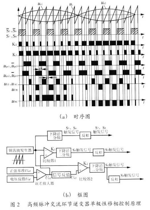
1.2单极性移相控制原理 以全桥全波式电路为例,其单极性移相控制原理,如图2所示。
当输入电压Ui降低或负载变大时,导致输出电压Uo.降低,闭环反馈控制使得移相角θ减小、共同导通时间Tcom增大,从而使得输出电压增大。因此.调节移相角θ可实现输出电压的稳定。 2 稳态原理与外特性
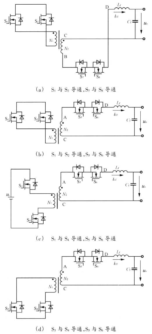
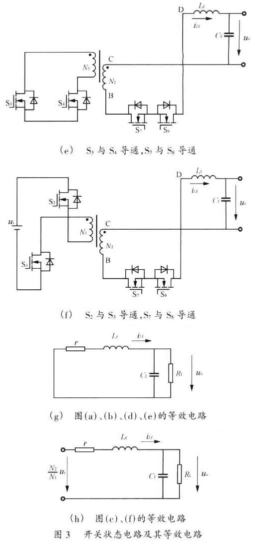
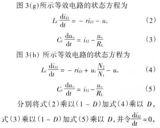
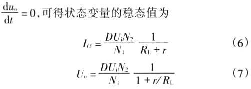
Fig.3 The switching state circuits and equivalent circuits 式中:D为滤波器前端电压SPWM波在一个开关周期内的占空比,即D=2Tcom/Ts=(180°-θ)/180°。 2.2 稳态时逆变器外特性
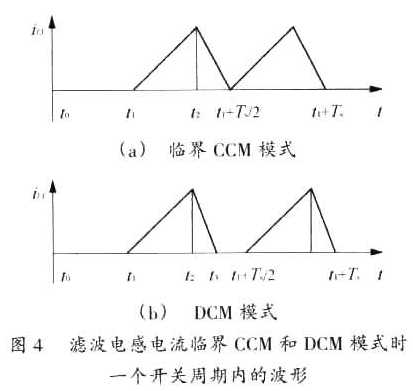
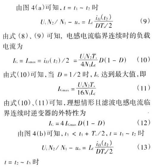
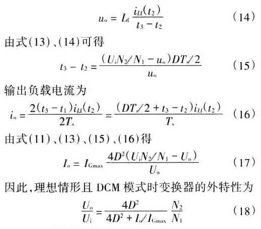
Fig.4 The filter inductance current waveforms in critically CCM and DCM during one switching period
3 原理试验 设计实例:全桥桥式电路拓扑,单极性移相控制策略,输入电压Ui=DC270(1±10%)V,输出电压Uo=AC115V/400Hz,额定容量S=1kV·A,开关频率fs=50kHz,变压器原、副边匝比为N1/N2=25/20,变压器磁芯选用Mn-Zn铁氧体R2KBD材料PM62×49,滤波电感Lf=0.5mH,滤波电容Cr=2μF,功率开关S1-S8b均选用IRFP460MOSFET(20A/500V),控制电路采用两片UC3879芯片。 逆变器额定阻性负载时原理试验波形,如图6所示.原理试验结果均表明:
1)变压器原边绕组电压uEF为双极性三态的高频脉冲交流电压波;
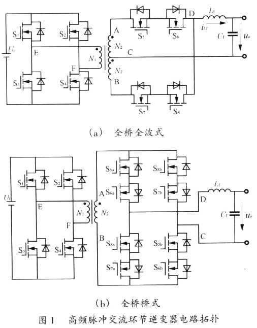
2)单极性移相控制高频脉冲交流环节逆变器拓扑包括全桥全波式、全桥桥式两种; 您打印的此文来自: |
|
| 作者:陈道炼 张… 来源:《电源技术应用》-2005年8卷5期 点击数: |
| - | 【字体:小 大】 |
